Boards need to be installed in the designated slots in a subrack. The subrack runs on -48 V DC or -60 V DC and is divided into multiple areas in which boards are powered by designated PIU boards in different slots. The subrack can be installed in an ETSI cabinet or a 19-inch cabinet.
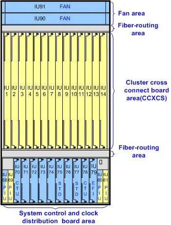
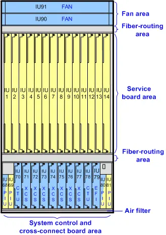
U16 can be used as a service subrack or a central cluster chassis. The function of a U16 subrack depends on the installed system control board. If the TNS1CTU board is installed, the U16 subrack functions as a common service subrack. Figure 1 shows the slots and areas in the Service subrack. If the TNS2CTU board is installed, the U16 subrack functions as a central cluster chassis. Figure 2 shows the slots and areas in the central cluster chassis. If an area has the same background color as a PIU board, then the PIU board powers the boards located in this area.
Figure 1 Schematic diagram of the areas and slots in the OptiX OSN 9800 U16 subrack (service subrack)
Table 1 Descriptions of the areas and slots in the OptiX OSN 9800 U16 subrack (service subrack)
| Area | Composition | Slot | Function |
|---|---|---|---|
| System control and cross-connect board area | 4 PIU boards | IU68, IU69, IU80, IU81 | They supply power to the subrack.
The PIU boards in slots IU68 and IU80, and the PIU boards in slots IU69 and IU81 are in mutual backup. Therefore, the failure of any power input to the subrack does not affect the normal operation of the subrack. |
| 1 EFI board | IU79 | The EFI board provides maintenance and management interfaces. | |
| 2 CTU boards(TNS1CTU) | IU70, IU78 | The CTU boards manage the subrack, provide clock for service boards, and implement inter-NE communication.
Two CTU boards are configured for mutual backup. |
|
| 7 cross-connect boards (TNS1XCS/TNS1UXCS) | IU71-IU77 | The cross-connect boards groom services between service boards.
Cross-connect boards are configured in M:N backup mode. When a U16 subrack is used as a pure regeneration subrack, no cross-connect board is required. |
|
| Fan area | 2 fan tray assemblies | IU90, IU91 | Fan tray assemblies are used to ventilate the equipment. |
| Fiber-routing areas | 2 fiber troughs | N/A | Fiber patch cords connecting to boards are routed to the left or right side of the equipment through the upper- and lower-side fiber troughs. |
| Service board area | 14 service boards | IU1-IU14 | Service boards need to be configured based on the service plan and all of them are installed in the service board area. |
Figure 2 Schematic diagram of the areas and slots in the OptiX OSN 9800 U16 subrack (central cluster chassis)

Table 2 Descriptions of the areas and slots in the OptiX OSN 9800 U16 subrack (central cluster chassis)
| Area | Composition | Slot | Function |
|---|---|---|---|
| System clock and control board area | 4 PIU boards | IU68, IU69, IU80, IU81 | They supply power to the subrack.
The PIU boards in slots IU68 and IU80, and the PIU boards in slots IU69 and IU81 are in mutual backup. Therefore, the failure of any power input to the subrack does not affect the normal operation of the subrack. |
| 1 EFI board | IU79 | The EFI board provides maintenance and management interfaces. | |
| 2 CTU boards(TNS2CTU) | IU70, IU78 | The CTU boards manage the subrack, provide clock for service boards, and implement inter-NE communication.
Two CTU boards are configured for mutual backup. |
|
| 2 system clock distribution boards (TNS1STD) | IU75, IU77 | Implements system clock processing and distribution for a cluster. | |
| Fan area | 2 fan tray assemblies | IU90, IU91 | Fan tray assemblies are used to ventilate the equipment. |
| Fiber-routing areas | 2 fiber troughs | N/A | Fiber patch cords connecting to boards are routed to the left or right side of the equipment through the upper- and lower-side fiber troughs. |
| Cluster cross-connect board area | 14 cross-connect boards(TNU1CCXCS) | IU1-IU14 | Implements centralized grooming of inter-subrack services for a cluster. |
NOTE:


Leave a comment