Description
OSN1500B Overview
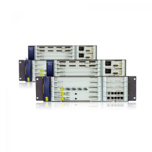
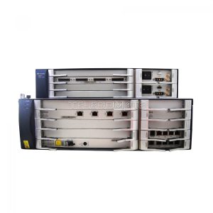
An OptiX OSN 1500B subrack has a two-layer structure. The subrack consists of a processing board area, an interface board area, an auxiliary interface board area, a power interface board area, a fan area and a cable routing area.
The functions of the areas are as follows:
- Interface board area: This area houses the tributary interface boards and Ethernet interface boards of the OptiX OSN 1500B.
- Power interface board area: This area houses two power interface boards, which supply power to the equipment.
- Fan area: This area houses one fan module, which dissipates heat generated by the equipment.
- Processing board area: This area houses the line, tributary, and Ethernet processing boards of the OptiX OSN 1500B.
- Auxiliary interface board area: This area provides alarm interfaces, an orderwire phone interface, management and maintenance interfaces, and clock interfaces.
- Cable routing area: This area houses fiber jumpers and cables in a subrack.
OSN1500B Slot Allocation
An OptiX OSN 1500B subrack consists of an upper layer and a lower layer. The upper layer provides six slots for interface boards and power interface boards. The lower layer provides 11 slots (available before the division of slots) for processing boards and auxiliary boards. After slot division, there are 14 slots. The mappings between the slots for the access boards the slots for the processing boards and the mappings between paired slots are specified.
The slots in an OptiX OSN 1500B subrack are allocated as follows:
Slots for line unit, SCC unit, cross-connect unit, and timing unit integrated boards: slots 4-5
Slots for processing boards before division of slots: slots 6-9 and 11-13
Slots for processing boards after division of slots: slots 1-9 and 11-13
Slots for service interface boards: slots 14-17
Slot for an order wire board: slot 9 (also for a processing board)
Slot for an auxiliary interface board: slot 10
Slots for power interface boards: slots 18 and 19
Slot for a fan board: slot 20
OSN1500B Mapping Between Slots for Interface Boards and Slots for Processing Boards
| Slot for Processing Board | Slot for Interface Board |
|---|---|
| Slot 2 | Slot 14 |
| Slot 7 | Slot 15 |
| Slot 12 | Slots 14 and 15 |
| Slot 3 | Slot 16 |
| Slot 8 | Slot 17 |
| Slot 13 | Slots 16 and 17 |
NOTE:
The corresponding interface boards of the PD3, PL3, SEP1, and SPQ4 can be housed only in slots of even numbers.
For the OptiX OSN 1500B, slots 7 and 12, slots 8 and 13, slots 6 and 11 are three couples of slots:
- The boards housed in slots 7 and 12 share the interface board housed in slot 15. Therefore, slots 7 and 12 cannot house the boards with interfaces available on an interface board.
- The boards housed in slots 8 and 13 share the interface board housed in slot 17. Therefore, slots 8 and 13 cannot house the boards with interfaces available on an interface board.
- The boards housed in slots 11 and 6 share the interface boards housed in slots 15 and 17. Therefore, slots 11 and 6 cannot house the boards with interfaces available on an interface board.
NOTE:
The boards in slots 6 and 11 are protection boards. The board in slot 6 provides protection for the boards in slots 7 and 8, and the board in slot 11 provides protection for the boards in slots 12 and 13. According to the tributary protection switching (TPS) mechanism, the boards in slots 6 and 11 share the interface boards housed in slots 15 and 17.
Paired Slots
If overhead bytes pass through the backplane bus between two slots, the two slots are called paired slots. Paired slots achieves automatic transparent transmission of overhead bytes such as K bytes, D bytes, and E1 overhead bytes. This improves multiplex section protection (MSP) switching performance and protects orderwire and DCC communication with other NEs even after the system control board on the local NE cannot be detected.
| Slot Division Status | Paired Slot |
|---|---|
| Before division of slots | (Slot 4, Slot 5) |
| (Slot 6, Slot 9) | |
| (Slot 7, Slot 8) | |
| (Slot 12, Slot 13) | |
| After division of slots | (Slot 4, Slot 5) |
| (Slot 6, Slot 9) | |
| (Slot 7, Slot 8) | |
| (Slot 1, Slot 11) | |
| (Slot 2, Slot 12) | |
| (Slot 3, Slot 13) |



David –
Tuve algunos problemas con mi nuevo Huawei OSN1500B y envié un correo electrónico a su equipo de soporte para pedir ayuda. Su soporte técnico es muy profesional. Resolvieron mi problema. ¡Excelente!