


.svg)

.svg)

.svg)

.svg)


Description
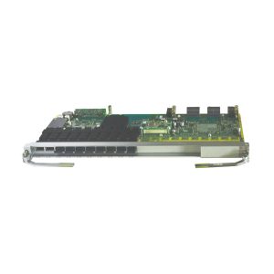
OSN 9800 U64 Standard overview
Intended for 100G and beyond 100G optical networks, the 9800 U64 Standard subrack is a next-generation large-capacity OTN product that integrates ASON, OTN, and packet functions. It is applicable to various networks, including super-backbone, backbone, and metro networks.
OSN 9800 U64 Standard subrack areas and slots
The OptiX OSN 9800 U64 equipment has integrated the OptiX OSN 9800 U64 subrack in a cabinet and provides board slots on both the front and rear sides. Boards need to be installed in the designated slots. 9800 U64 subracks are classified into two types, namely 9800 U64 Standard and 9800 U64 Enhanced

Descriptions of the areas and slots in the OptiX OSN 9800 U64 Standard subrack
| Area | Composition | Slot | Function | |
| Power and interface area | Front | 1 EFI board and 10 PIU boards | PIU: IU100-IU104, IU106-IU110 EFI: IU105 | The PIU boards on the front and rear sides are in mutual backup. Therefore, the failure of any power input to the equipment does not affect the normal operation of the equipment. NOTE: The PIU boards installed back-to-back are in mutual backup, for example, the PIU boards in slots IU100 and IU121, the PIU boards in slots IU101 and IU120, and so on. The EFI board provides maintenance and management interfaces. |
| Rear | 10 PIU boards | PIU: IU111-IU115, IU117-IU121 IU116: reserved | ||
| Fan areas | Front | 4 fan tray assemblies | Lower portion: IU90, IU91 Upper portion: IU92, IU93 | The fan tray assemblies are used to ventilate the equipment. |
| Rear | 4 fan tray assemblies | Lower portion: IU94, IU95 Upper portion: IU96, IU97 | ||
| Fiber-routing areas | Front | 2 fiber troughs | N/A | Fiber patch cords connecting to boards are routed to the left or right side of the equipment through the upper- and lower-side fiber troughs. |
| Rear | 2 fiber troughs | |||
| Service board areas | Front | 32 service boards | Lower portion: IU1-IU16 Upper portion: IU17-IU32 | Service boards need to be configured based on the service plan and all of them are installed in the two service board areas. NOTE: Service boards installed in slots IU1-IU16 and IU33-IU48 have their ejector levers on the right sides of the board front panels. Service boards installed in remaining slots in the two areas have their ejector levers on the left sides of the board front panels. |
| Rear | 32 service boards | Lower portion: IU33-IU48 Upper portion: IU49-IU64 | ||
| System control and cross-connect board area | Front | 2 CTU | Cross-connect board: IU71-IU77 | Cross-connect boards are configured in M:N backup mode to implement cross-connections for services boards on the front and rear sides. The system control boards are configured in 1+1 backup mode. The active system control board manages and provides a clock to all other boards in the equipment. It also provides for inter-NE communication. When a U64 subrack is used as a pure regeneration subrack, no cross-connect board is required. |
| CTU: IU70, IU78 | ||||
OSN 9800 U64 Standard cross-connect capacities
This topic describes the cross-connect capacity of a service slot and an OptiX OSN 9800 U64 subrack.
| Subrack Type | Maximum Cross-Connect Capacity of Each Slot | Maximum Cross-Connect Capacity of Subrack | ||||||||
| ODUk | OSUflex | VC-4 | VC-3/VC-12a | Packet | ODUk | OSUflex | VC-4 | VC-3/VC-12 | Packet | |
| Standard | 400 Gbit/s | 400 Gbit/s | 160 Gbit/s | 160 Gbit/s | 400 Gbit/s | 25.6 Tbit/s | 25.6 Tbit/s | 10.24 Tbit/s | 160 Gbit/s | 25.6 Tbit/s |
| Enhanced | 1Tbit/s | 1Tbit/s | 160 Gbit/s | 160 Gbit/s | 400 Gbit/s | 64 Tbit/s | 64 Tbit/s | 10.24 Tbit/s | 160 Gbit/s | 25.6 Tbit/s |
| a: All service slots share a bandwidth of 160 Gbit/s. | ||||||||||


Martina –
I bought this equipment from you last month. It works great. Now I want to know if you have the cards for this equipment?
Beverly –
The accompanying network management system is feature-rich and intuitive, making fault detection and traffic analysis very convenient, which greatly improves operational efficiency.