


.svg)

.svg)

.svg)

.svg)


Description
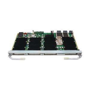
OSN 9800 U64 Enhanced overview
Intended for 100G and beyond 100G optical networks, the 9800 U64 Enhanced subrack is a next-generation large-capacity OTN product that integrates ASON, OTN, and packet functions. It is applicable to various networks, including super-backbone, backbone, and metro networks.
OSN 9800 U64 Enhanced subrack areas and slots

osn9800 u64 enhanced subrack areas and slots
Descriptions of the areas and slots in the OptiX OSN 9800 U64 Enhanced subrack
| Area | Composition | Slot | Function | |
| Power and interface area | Front | 1 EFI board and 10 PSU boards | PSU: IU100-IU104, IU106-IU110 | The PSUs of the subrack work in N+N (6 ≤ N ≤ 10) backup mode. The failure of any N power inputs does not affect the normal running of the device. |
| EFI: IU105 | The EFI board provides maintenance and management interfaces. | |||
| Rear | 10 PSU boards | PSU: IU111-IU115, IU117-IU121 | ||
| IU116: reserved | ||||
| Fan areas | Front | 4 fan tray assemblies | Lower portion: IU90, IU91 | The fan tray assemblies are used to ventilate the equipment. |
| Upper portion: IU92, IU93 | ||||
| Rear | 4 fan tray assemblies | Lower portion: IU94, IU95 | ||
| Upper portion: IU96, IU97 | ||||
| Fiber-routing areas | Front | 2 fiber troughs | N/A | Fiber patch cords connecting to boards are routed to the left or right side of the equipment through the upper- and lower-side fiber troughs. |
| Rear | 2 fiber troughs | |||
| Service board areas | Front | 32 service boards | Lower portion: IU1-IU16 Upper portion: IU17-IU32 | Service boards need to be configured based on the service plan and all of them are installed in the two service board areas. NOTE: Service boards installed in slots IU1-IU16 and IU33-IU48 have their ejector levers on the right sides of the board front panels. Service boards installed in the remaining slots in the two areas have their ejector levers on the left sides of the board front panels. |
| Rear | 32 service boards | Lower portion: IU33-IU48 Upper portion: IU49-IU64 | ||
| System control and cross-connect board area | Front | 2 CTU system control boards and 7 cross-connect boards | Cross-connect board: IU71-IU77 CTU: IU70, IU78 | Seven cross-connect boards of the U64 Enhanced subrack form a cross-connect resource pool for service grooming. When two UCXCS boards are faulty, the system can still function properly. If more than two UCXCS boards become faulty, the system will fail. The cross-connect boards provide cross-connections for service boards. The system control boards are configured in 1+1 backup mode. The active system control board manages and provides a clock to all other boards in the equipment. It also provides for inter-NE communication. |
| Rear | 7 cross-connect boards | Cross-connect board: IU79-IU85 | ||
OSN 9800 U64 Enhanced cross-connect capacities
This topic describes the cross-connect capacity of a service slot and an OptiX OSN 9800 U64 subrack.
| Subrack Type | Maximum Cross-Connect Capacity of Each Slot | Maximum Cross-Connect Capacity of Subrack | ||||||||
| ODUk | OSUflex | VC-4 | VC-3/VC-12a | Packet | ODUk | OSUflex | VC-4 | VC-3/VC-12 | Packet | |
| Standard | 400 Gbit/s | 400 Gbit/s | 160 Gbit/s | 160 Gbit/s | 400 Gbit/s | 25.6 Tbit/s | 25.6 Tbit/s | 10.24 Tbit/s | 160 Gbit/s | 25.6 Tbit/s |
| Enhanced | 1Tbit/s | 1Tbit/s | 160 Gbit/s | 160 Gbit/s | 400 Gbit/s | 64 Tbit/s | 64 Tbit/s | 10.24 Tbit/s | 160 Gbit/s | 25.6 Tbit/s |
| a: All service slots share a bandwidth of 160 Gbit/s. | ||||||||||


Ashley –
The device supports the transmission of OTN, SDH, and Ethernet services simultaneously, meeting our diverse business needs and reducing the number of devices required.