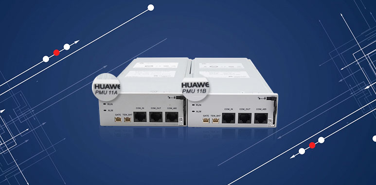
This article will introduce PMU 11A and PMU 11B monitoring module for ETP48100-B1, is there any difference between them? The answer is that PMU 11A and PMU 11B can replace each other without any difference.
PMU 11A or PMU 11B Exterior
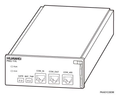
The following figure shows the exterior of a PMU 11A or PMU 11B.
Figure 1 Exterior of a PMU 11A or PMU 11B

A power monitoring unit 11A or 11B (PMU 11A or PMU 11B) manages a power system and batteries, monitors power distribution, and reports alarms. A PMU 11A or PMU 11B can be used in an IMS06 subrack or in any of the following cabinets: BTS3900 (Ver.D), BTS3900L (Ver.D), BTS3900AL (Ver.A), OMB (Ver.C), IMB03, IMB05, IBC10, BTS3900 (Ver.D_A), BTS3900 (Ver.D_B), APM30H (Ver.D), APM30H (Ver.D_A1), APM30H (Ver.D_A2), APM30H (Ver.E_A1), APM30H (Ver.D_B), BTS3012 (Ver.D_Z), and BTS3012AE (Ver.D_Z).
Function
A PMU 11A or PMU 11B performs the following functions:
- Communicates with an upper-level device through an RS485 port.
- Manages a power system and the charge and discharge of storage batteries.
- Monitors the door status and the temperature of storage batteries.
- Monitors power distribution and reports alarms.
Communicates with a battery cabinet through an RS485 port.
Port
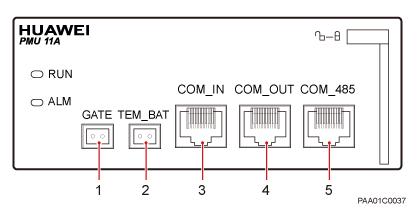
The following figure shows the ports on a PMU 11A or PMU 11B.
Figure 2 Ports on a PMU 11A or PMU 11B

The following table describes the ports on a PMU 11A or PMU 11B.
| Table 1 Ports on a PMU 11A or PMU 11B | |||
| No. | Silkscreen | Connector | Description |
| 1 | GATE | 2-pin connector | Connects to a cabinet door status sensor |
| 2 | TEM_BAT | 2-pin connector | Connects to a storage battery temperature sensor |
| 3 | COM_IN | RJ45 connector | Connects to a BBU for communication or communicates with an upper-level monitoring board |
| 4 | COM_OUT | RJ45 connector | Communicates with a lower-level monitoring board for communication |
| 5 | COM_485 | RJ45 connector | Connects to the monitoring board in a battery cabinet, and receives monitoring signals from the battery cabinet |
Indicator
The following table describes the indicators on a PMU 11A or PMU 11B.
| Table 2 Indicators | ||||
| Silkscreen | Meaning | Color | Status | Description |
| RUN | Running indicator | Green | Steady on | The board is being started, conducting self-check, or being loaded and activated. |
| Blinking (on for 1s and off for 1s) | The module is functional and is properly communicating with the main control board in a BBU. | |||
| Blinking (on for 0.125s and off for 0.125s) | The module is functional but unable to properly communicate. | |||
| Steady off | The module is faulty, or there is no DC power supply. | |||
| ALM | Alarm indicator | Red | Steady on | An alarm has been generated, and the module needs to be replaced. |
| Steady off | No alarm has been generated. | |||
| Blinking (on for 1s and off for 1s) | An alarm has been generated, and you need to locate the fault before determining whether to replace the module. | |||
DIP Switch
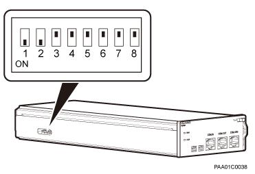
There is a DIP switch on the left panel of a PMU 11A or PMU 11B. A DIP switch has eight bits, where the four least significant bits (1, 2, 3, and 4) define the monitoring address of a PMU 11A or PMU 11B, and the four most significant bits (5, 6, 7, and 8) are not defined but reserved for future use. ON is indicated by 1, and OFF is indicated by 0. The monitoring address of a PMU 11A or PMU 11B is set to 3 by default before delivery, as shown in the following figure.
Figure 3 DIP switch on the left panel of a PMU 11A or PMU 11B

At a site configured with two or more APM30Hs, if two PMU units are connected to one RS485 bus for the BBU, the monitoring address of the other PMU is set to 4. That is, the lower four bits of the DIP switch are set to 0010.
If you have any questions, please feel free to contact csd@telecomate.com.

Leave a comment