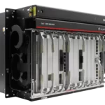
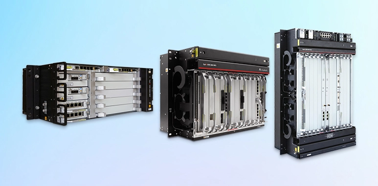
The next-generation M series subracks feature large capacity, optical-electrical integration, and small size. The M series subracks apply to integrated bearing scenarios, such as broadband video, mobile backhaul, enterprise private line, and DCI, and provide an optimal end-to-end transmission solution from the backbone layer, aggregation layer, to access layer.
| Specifications | 9800 M24 | 9800 M12 | 9800 M05 | |
|---|---|---|---|---|
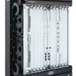
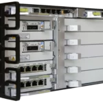
| Product appearance |  |
|
||
| Subrack dimensions (mm) | 747.2 (H) x 442 (W) x 295 (D) | 347.2 (H) x 442 (W) x 295 (D) | 177 (H) x 442 (W) x 295 (D) | |
| Suitable cabineta |
|
|||
| Max. number of service board slots | 1:1 cross-connect mode: 12 large slots or 24 small slots
1:3 cross-connect mode: 10 large slots or 20 small slots NOTE: The M24 subrack supports slot splitting. One 11 U slot of the M24 subrack can be split into two 5.5 U slots. |
13 | 5 | |
| Switching capability | Optical | 1 to 20-degree reconfigurable optical add/drop multiplexer (ROADM) | ||
| Electrical |
|
N/A | ||
| Max. number of wavelengths |
|
|||
| Wavelength range | DWDM system: 1524.50 nm to 1572.06 nm (C120 band)
DWDM: 1575.37 nm to 1626.21 nm (L120 Band) CWDM system: 1471 nm to 1611 nm (S+C+L band) |
|||
| Max. rate per channel | 800 Gbit/s (OTUC8) | |||
| Service type | SDH, SONET, PDH, Ethernet, SAN, OTN, Video, OSU | SDH, SONET, Ethernet, SAN, OTN, Video | ||
| Packet service capacity |
|
N/A | ||
| Line rate | 1.25 Gbit/s, 2.5 Gbit/s, 10 Gbit/s, 25 Gbit/s, 100 Gbit/s, 200G bit/s, 300Gbit/s, 400G bit/s, 600G bit/s, 800G bit/s | 10 Gbit/s, 100 Gbit/s, 200G bit/s, 300Gbit/s, 400G bit/s, 600G bit/s, 800G bit/s | ||
| Supported pluggable optical modules | eSFP, SFP+, TSFP+, CFP, CSFP, CFP2, QSFP28, SFP28, TSFP28, QSFP+, QSFP-DD | eSFP, SFP+, TSFP+, CFP, CSFP, CFP2, QSFP28, SFP28, QSFP+, QSFP-DD | ||
| Topology | Point-to-point, chain, star, ring, ring-with-chain, tangent ring, intersecting ring, and mesh | |||
| Redundancy and protection | Network level protection (OTN) | Optical line protection, client 1+1 protection, ODUk SNCP, OSUflex SNCP, tributary SNCP, intra-board 1+1 protection, LPT | Optical line protection, client 1+1 protection, intra-board 1+1 protection, LPT, intra-board ODUk SNCP, tributary SNCP | |
| Network level protection (Packet) | ERPS, LAG, PW APS/FPS, Tunnel APS, MC-LAG, MC-PW APS, LPT | N/A | ||
| Network Level Protection (SDH) | SNCP, linear MSP, ring MSP, TPS | N/A | ||
| Network level protection (EoS) | LAG, DLAG, LCAS, LPT, STP/RSTP, BPS, PPS | N/A | ||
| Equipment level protection | Power supply redundancy, fan redundancy, cross-connect board redundancy, communication control and clock processing unit redundancy | Power supply redundancy, fan redundancy, communication control unit redundancy, clock processing unit redundancy
|
||
| Encryption type | Client-side service encryption | |||
| Optical power management | ALS, ALC, IPA, IPA of the Raman system, IPC | |||
| Easy O&M | Optical Doctor (OD) system, Fiber Doctor (FD) system | |||
| Synchronization | Synchronous Ethernet, IEEE 1588v2, ITU-T G.8275.1/G.8273.2, high-precision clock synchronization | |||
| ASON |
|
Optical-layer ASON | ||
| TSDN |
|
|||
| Submarine cable features | Supports application of extended C band in submarine cable scenarios. | N/A | N/A | |
| Power supply | DC power input
AC power input
High-voltage DC power input
NOTE: In IEEE1613-compliant scenarios: (There is no such requirement when other standards are used.):
|
DC power input
AC power input
High-voltage DC power input
NOTE: In IEEE1613-compliant scenarios: (There is no such requirement when other standards are used.):
|
||
| Operation environment | Subrack temperature:
Relative humidity:
|
Subrack temperature:
Relative humidity:
|
Subrack temperature:
Relative humidity:
|
|
| Mean Time To Repair (MTTR) | 1 hoursc
NOTE: Average time for only fault locating, board replacement, device restart, and service recovery, excluding component preparation and transportation time. |
|||
| Mean Time Between Failure (MTBF) | 65.94 yearsc | |||
| Availability | 0.999993076c | |||
| a: The ETSI/19-inch standard defines only part of the cabinet dimensions. Therefore, the distance between the cabinet column and door plate varies depending on cabinet manufacturers. For details about the dimensions of different subracks, see the detailed description of each subrack.
b: Short-term operation means that the continuous operating time does not exceed 96 hours and the accumulated time per year does not exceed 15 days. c: The preceding parameters are calculated based on the typical product configuration. In actual use, these parameters vary according to the configured module. |
||||
If you have any questions, please feel free to contact: csd@telecomate.com


Leave a comment