Friends and members of the forum, I want to share with you how to insert an SDH (Synchronous Digital Hierarchy) network element to a ring-type topology, it is very common that as network administrators we are presented with this type of situation, I want in this publication offer you the way to do it regardless that there may be several.
If we start from a network in the process of expansion and that you as an operator need to insert a network element to a ring-type topology. The network administrator must take a series of actions into account for the node insertion to be successful.
We start from a ring-type topology, the network elements involved are optix OSN500, the SDH level of the ring is 622.52 Mbps (STM4), the names of the network elements are NE15555, NE15556, NE15557. The new network device that will be part of the ring is the network element named NE15558.
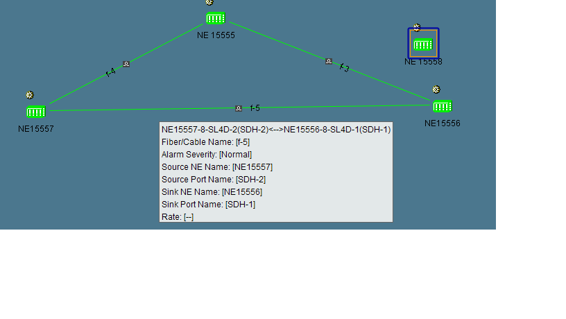
the question is how to do it.
First it is necessary to write down which are the logical connections that unite the involved devices, standing over with the mouse it visualizes the existing connection.
Then you have to enter the two network elements (NE 15557 and NE15556) and write down the existing cross connections in each node, for this you have to do the following.
Right click on NE 15557-> NE Explorer-> Configuration-> SDH / PDH Service Management
Right click on NE 15556-> NE Explorer-> Configuration-> SDH / PDH Service Management
We write down the Cross Connections in each node and we concentrate on the line ports involved (NE 15557 Line 8-SLD4-2 and NE 15556 Line 8-SLD4-1), we create a virtual node this time with the same characteristics of the NE 15558 node and we make the cross connections at a logical level, this cros connections can be at the VC12 level as well as at the VC3 level.
Example NE 15557

Example NE 15556

NE 15558 (Node to be inserted in the network)
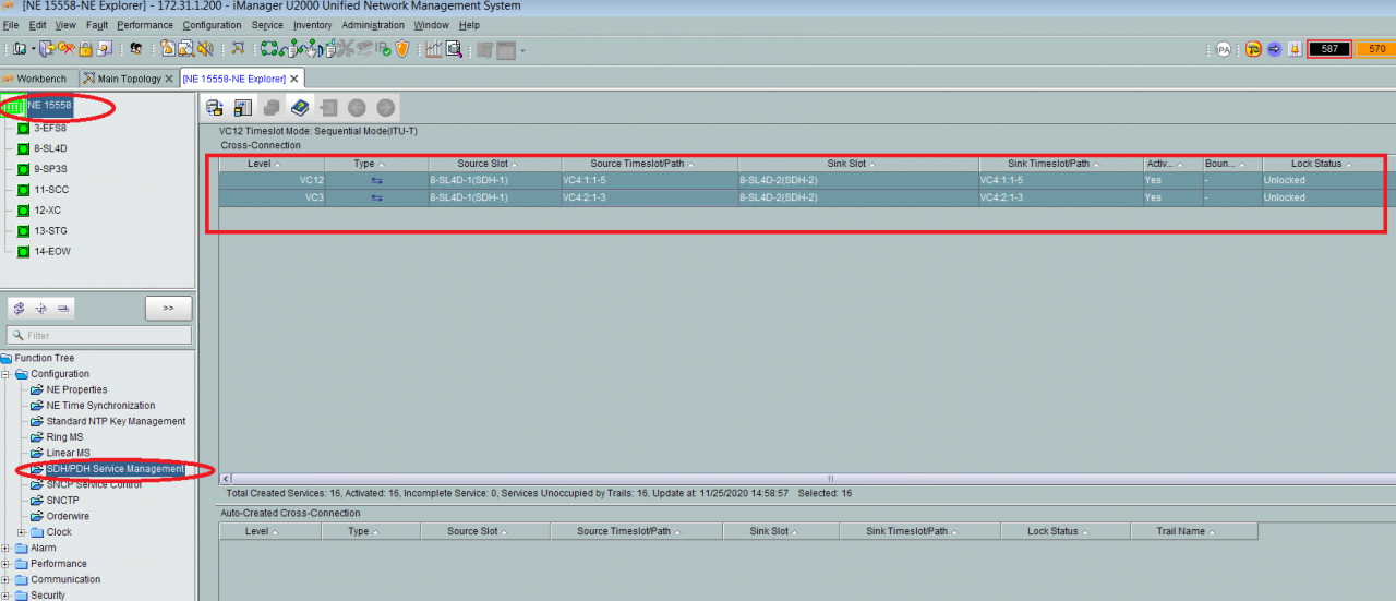
Then we erase the fiber that joins the NE 15557 and NE 15556 devices, making the following route.
From the client U2000-> Inventary-> Fiber / CableMicrowave Link -> Cable Microwave Link Management.
Then a window will be displayed in which we must go to Filter-> Source NE, in Source NE we select the two network elements in which we need to erase the fiber.
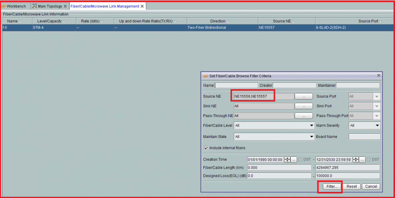

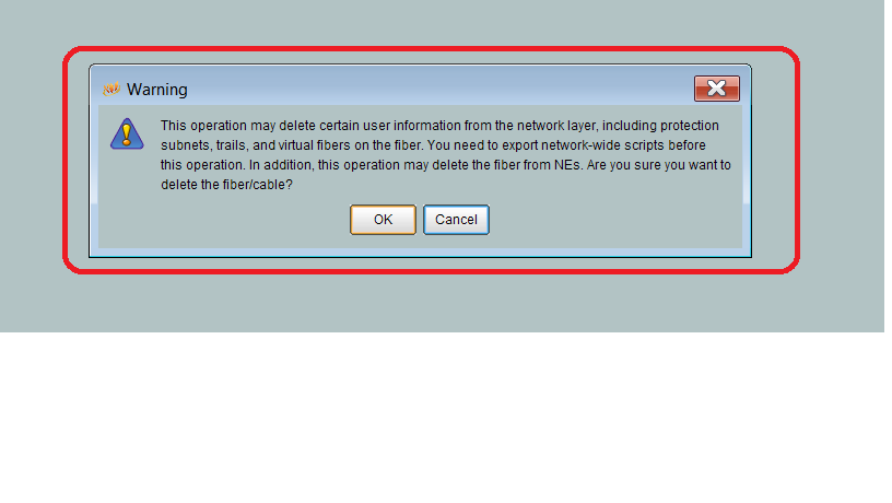
We give the option ok.
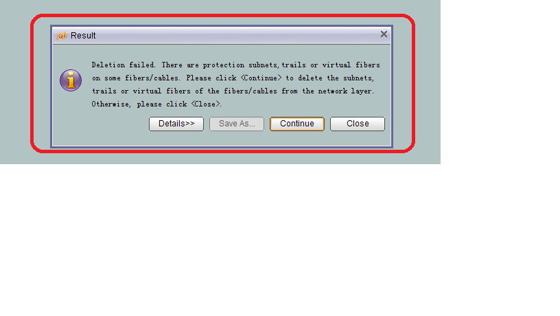
The services are automatically no longer seen from the management system, therefore, you give the Continue option.

Once this is done you manually create the fibers between the nodes involved, the line card of the node NE 15557 with ease 8-SLD4-2 vs NE 15558 ease 8-SLD4-1 and the latter 8-SLD4-2 VS NE 15556 ease 8-SLD4-1.


Once the cross connections have been made in the NE 15558 and the physical connection is made as previously written, a download is made to the NE and after doing it you must perform a path search from the management system and integrity of the services in this layer must be complete.
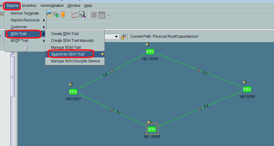
After the services are in the management plane, you concentrate on configuring the synchronism in the NE, the auto synchronization of the NE with the NMS, as well as the performance activation for both 15 Minutes and 24 hours.
By doing these actions you learned how to insert a network element in a ring topology.

Leave a comment