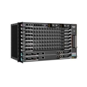
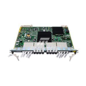
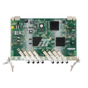
AN6000-17

2 Reviews Write a review
SKU2009572
AvailabilityIn Stock
WarrantyUp to 36 months i
×
Warranty Policy
We provide a comprehensive warranty policy.
Refer to the table for more details.

Fiberhome AN6000-17 OLT supports 17 service slots,  with 2* HSCA core switch cards and 2* PIBA DC power cards

Description

AN6000-17 overview

The AN6000-17 is a large-sized optical line terminal deployed in a central office. Providing 17 service slots and featuring large capacity and high bandwidth, the device can cater to the access demand in a densely-populated area.

AN6000-17 is the next-generation OLT platform that has the ultra-broadband capability for PON smooth evolution. Their distributed architecture design can support high-density GPON, XG(S)-PON, XG(S)-PON Combo, TWDM-PON, WDM-PON, and P2P card, which will bring higher bandwidth and enhance capacity for access network. Cloudization and virtualization can also be implemented on them. All of these will improve user experience, and reduce long-term investment and maintenance costs of operators.


AN6000-17 appearance and structure

AN6000-17  slot distribution

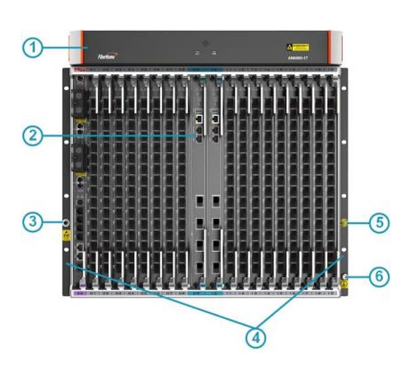
No. Name Function
1 Vertical card slot Houses a fan unit.
2 Horizontal card slot Accommodates cards to implement various functions of the equipment.
3 ESD protection earth ground fastener Connects with an ESD protection unit.
 4 Mounting ears Secure the subrack in a cabinet
5 Fiber puller hanger Holds a fiber puller.
6 Subrack earth ground point Connects with the subrack protection earth ground cable.


AN6000-17  slot distribution

The AN6000-17 subrack provides 12 horizontal slots and one vertical slot.
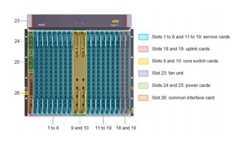
AN6000-17  slot distribution

AN6000-17 card supported

The slots can be classified as follows according to the cards they house:

Type Slot Card Supported
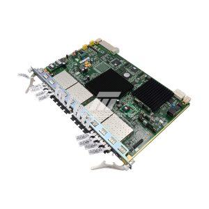
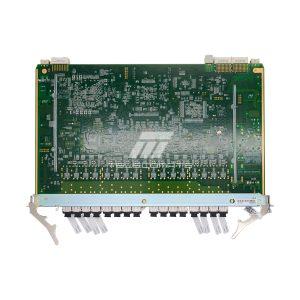
Service card slot  1-8 and 11- 19 GPOA, EX8A, EXOA, GX8A, GM8A, GM8B, GMOA, GNOA, GFOA and PXNA
Uplink card slot  18-19 HU8A, KU1B
Core switch card slot 8-9 HSCA
Fan unit slot 23 FAN
Power card slot 24-25 PIBA
Common interface card slo 26 CIOA
Item AN6000-17
Slot configuration Two slots for core switch cards (slots 9 and 10) 17 slots for service cards (slots 1 to 8 and 11 to 19) Two slots for uplink cards (slots 18 and 19) Two slots for power cards (slots 24 and 25) One slot for the common interface card (slot 26) One slot for the fan unit (slot 23)
Dimensions (H × W × D) of a subrack with mounting ears for 21-inch cabinetsNote 1 486 mm × 530 mm × 282 mm
Weight of an empty subrack (excluding the fan unit) 14 kg
Weight of an empty subrack (including the fan unit) 19 kg
Maximum input current 63 A
Power supply mode DC (two channels of power supplies forming redundancy protection)
Working voltage range -38.4 V to -57.6 V
Rated voltage -48 V
Operating temperature -40℃ to 65℃
Operating relative humidity 5% to 95% (non-condensing)
Storage temperature -40℃ to 70℃
Relative humidity for storage 5% to 95% (non-condensing)
Atmospheric pressure 70 kPa to 106 kPa
Slot bandwidth 200 Gbit/s
Switch capacity of the backplane bus 13.6 Tbit/s
Core switch card capacity (in the load sharing mode) 6.8 Tbit/s
Maximum number of MAC addresses in the system 262144
Maximum number of IPv4 routing tables in the system 16384
Maximum number of IPv6 routing tables in the system 8192
Maximum number of ARP tables in the system 18432
Maximum number of ND tables in the system 9216
Maximum number of multicast groups in the system 4096
Full-load bit error rate < 10 e-7
System reliability specifications System availability with typical configuration:  > 99.999% Mean time between failures (MTBF) of the system: approx. 45 years Note: The mean time to repair (MTTR) for the entire system is 2 hours.
Maximum number of GPON ports in the system 272
Maximum number of 10G EPON ports in the system 272
Maximum number of XG-PON ports in the system 272
Maximum number of GPON & XG-PON Combo ports in the system 272
Maximum number of GPON & XGS-PON Combo ports in the system 272
Maximum number of Agile-PON ports in the system 272
Maximum number of uplink ports in the system 8 × 10GE / GE uplink ports (HSCA) (Only core switch cards are used to provide uplink ports.)
16 × 10GE / GE uplink ports (HU8A) + 8 × 10GE / GE uplink ports (HSCA) (Both core switch cards and uplink cards are used to provide uplink ports.)
8 × 10GE / GE uplink ports (KU1B) + 2 × 100GE uplink ports (KU1B) + 8 × 10GE / GE uplink ports (HSCA) (Both core switch cards and uplink cards are used to provide uplink ports.)
Maximum number of Ethernet ports in the system 408
Maximum number of ONUs connected to the system 17408
Maximum number of multicast users in the system 17408
Maximum transmission distance (PON port) 60 km
Maximum uplink transmission distance 80 km
Time for active-standby switching of core switch cards / uplink cards ≤ 50 ms
Time for optical path protection switching (Type B / Type C) ≤ 50 ms
Bandwidth allocation granularity of DBA GPOA: 64 kbit/s
EX8A: 640 kbit/s
EXOA: 640 kbit/s
GX8A: 256 kbit/s
GM8A: 256 kbit/s (XG-PON) / 64 kbit/s (GPON)
GM8B: 256 kbit/s (XG-PON) / 64 kbit/s (GPON)
GMOA: 256 kbit/s (XG-PON) / 64 kbit/s (GPON)
GNOA: 64 kbit/s (XGS-PON) / 64 kbit/s (GPON)
GFOA: 64 kbit/s (XGS-PON) / 256 kbit/s (XG-PON) / 64 kbit/s (GPON)
Minimum configurable bandwidth of DBA GPOA: 1024 kbit/s
EX8A: 2560 kbit/s
EXOA: 2560 kbit/s
GX8A: 1024 kbit/s
GM8A: 1024 kbit/s
GM8B: 1024 kbit/s
GMOA: 1024 kbit/s
GNOA: 1024 kbit/s
GFOA: 1024 kbit/s
DBA accuracy Better than ±5%
Long-term packet loss rate When the traffic accounts for 90% of the throughput, the 24-hour packet loss rate is 0.
Overall power consumption Typical configuration: 2 × HSCA + 17 × GNOA + 2 × PIBA + FAN + CIOA Static power consumption: 1211 W Typical power consumption: 2093 W Maximum power consumption: 2449 W The equipment can only be used together with a PDP with a rated current of 63 A. For details of the matching PDPs, see PDPs. Note: For other card configurations, calculate the overall power consumption according to this formula: overall power consumption = power consumption of 2 core switch cards + power consumption of 17 service cards + power consumption of 2 power cards + power consumption of the fan unit + power consumption of the common interface card. For power consumption of each card, refer to AN6000 Series Optical Line Terminal Equipment Hardware Description.
Note 1: The AN6000- 17 subrack is equipped with the mounting ears for 21-inch cabinets by default.

Additional information

Dimensions 49 × 53 × 29 cm
Brand

Fiberhome

Lead Time

3-5 days

Ship From

Shenzhen Warehouse

Item AN6000-17
Slot configuration Two slots for core switch cards (slots 9 and 10) 17 slots for service cards (slots 1 to 8 and 11 to 19) Two slots for uplink cards (slots 18 and 19) Two slots for power cards (slots 24 and 25) One slot for the common interface card (slot 26) One slot for the fan unit (slot 23)
Dimensions (H × W × D) of a subrack with mounting ears for 21-inch cabinetsNote 1 486 mm × 530 mm × 282 mm
Weight of an empty subrack (excluding the fan unit) 14 kg
Weight of an empty subrack (including the fan unit) 19 kg
Maximum input current 63 A
Power supply mode DC (two channels of power supplies forming redundancy protection)
Working voltage range -38.4 V to -57.6 V
Rated voltage -48 V
Operating temperature -40℃ to 65℃
Operating relative humidity 5% to 95% (non-condensing)
Storage temperature -40℃ to 70℃
Relative humidity for storage 5% to 95% (non-condensing)
Atmospheric pressure 70 kPa to 106 kPa
Slot bandwidth 200 Gbit/s
Switch capacity of the backplane bus 13.6 Tbit/s
Core switch card capacity (in the load sharing mode) 6.8 Tbit/s
Maximum number of MAC addresses in the system 262144
Maximum number of IPv4 routing tables in the system 16384
Maximum number of IPv6 routing tables in the system 8192
Maximum number of ARP tables in the system 18432
Maximum number of ND tables in the system 9216
Maximum number of multicast groups in the system 4096
Full-load bit error rate < 10 e-7
System reliability specifications System availability with typical configuration:  > 99.999% Mean time between failures (MTBF) of the system: approx. 45 years Note: The mean time to repair (MTTR) for the entire system is 2 hours.
Maximum number of GPON ports in the system 272
Maximum number of 10G EPON ports in the system 272
Maximum number of XG-PON ports in the system 272
Maximum number of GPON & XG-PON Combo ports in the system 272
Maximum number of GPON & XGS-PON Combo ports in the system 272
Maximum number of Agile-PON ports in the system 272
Maximum number of uplink ports in the system 8 × 10GE / GE uplink ports (HSCA) (Only core switch cards are used to provide uplink ports.)
16 × 10GE / GE uplink ports (HU8A) + 8 × 10GE / GE uplink ports (HSCA) (Both core switch cards and uplink cards are used to provide uplink ports.)
8 × 10GE / GE uplink ports (KU1B) + 2 × 100GE uplink ports (KU1B) + 8 × 10GE / GE uplink ports (HSCA) (Both core switch cards and uplink cards are used to provide uplink ports.)
Maximum number of Ethernet ports in the system 408
Maximum number of ONUs connected to the system 17408
Maximum number of multicast users in the system 17408
Maximum transmission distance (PON port) 60 km
Maximum uplink transmission distance 80 km
Time for active-standby switching of core switch cards / uplink cards ≤ 50 ms
Time for optical path protection switching (Type B / Type C) ≤ 50 ms
Bandwidth allocation granularity of DBA GPOA: 64 kbit/s
EX8A: 640 kbit/s
EXOA: 640 kbit/s
GX8A: 256 kbit/s
GM8A: 256 kbit/s (XG-PON) / 64 kbit/s (GPON)
GM8B: 256 kbit/s (XG-PON) / 64 kbit/s (GPON)
GMOA: 256 kbit/s (XG-PON) / 64 kbit/s (GPON)
GNOA: 64 kbit/s (XGS-PON) / 64 kbit/s (GPON)
GFOA: 64 kbit/s (XGS-PON) / 256 kbit/s (XG-PON) / 64 kbit/s (GPON)
Minimum configurable bandwidth of DBA GPOA: 1024 kbit/s
EX8A: 2560 kbit/s
EXOA: 2560 kbit/s
GX8A: 1024 kbit/s
GM8A: 1024 kbit/s
GM8B: 1024 kbit/s
GMOA: 1024 kbit/s
GNOA: 1024 kbit/s
GFOA: 1024 kbit/s
DBA accuracy Better than ±5%
Long-term packet loss rate When the traffic accounts for 90% of the throughput, the 24-hour packet loss rate is 0.
Overall power consumption Typical configuration: 2 × HSCA + 17 × GNOA + 2 × PIBA + FAN + CIOA Static power consumption: 1211 W Typical power consumption: 2093 W Maximum power consumption: 2449 W The equipment can only be used together with a PDP with a rated current of 63 A. For details of the matching PDPs, see PDPs. Note: For other card configurations, calculate the overall power consumption according to this formula: overall power consumption = power consumption of 2 core switch cards + power consumption of 17 service cards + power consumption of 2 power cards + power consumption of the fan unit + power consumption of the common interface card. For power consumption of each card, refer to AN6000 Series Optical Line Terminal Equipment Hardware Description.
Note 1: The AN6000- 17 subrack is equipped with the mounting ears for 21-inch cabinets by default.

Reviews

  1. Isam

    Thanks for the recommendation from my friend, so that I bought such a high-quality device.

  2. Ricardo

    Hemos comprado el AN6000-17 desde Telecomate.com. Todo está bien, pero debido el gran volumen, el costo de envio es costoso, en el pedido seguinete, nos preparamos entregar por el mar, va a ahorrar mucho para nosotros.

Add a review

Your email address will not be published. Required fields are marked *

Back to Top

Search For Products

Product has been added to your cart