1. Checking Whether the Switch Supports the Power Module
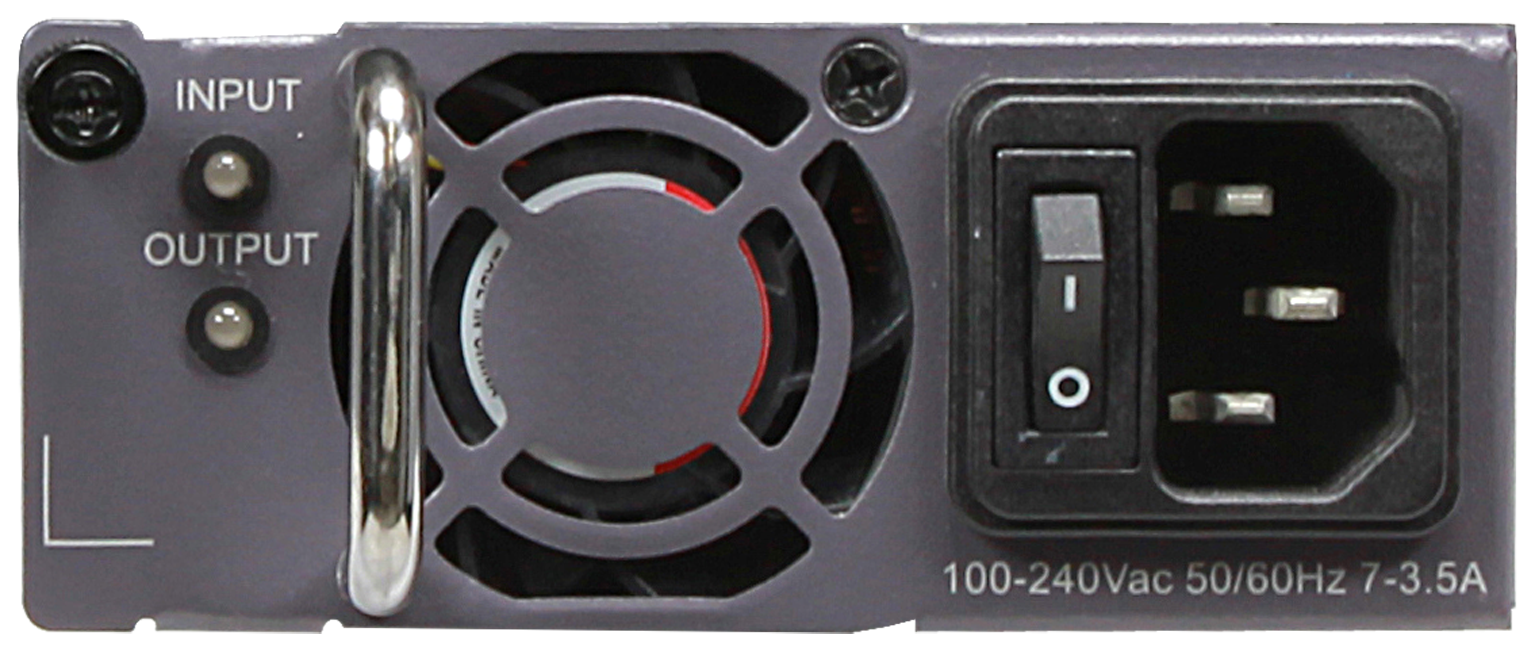
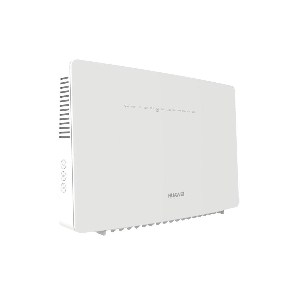
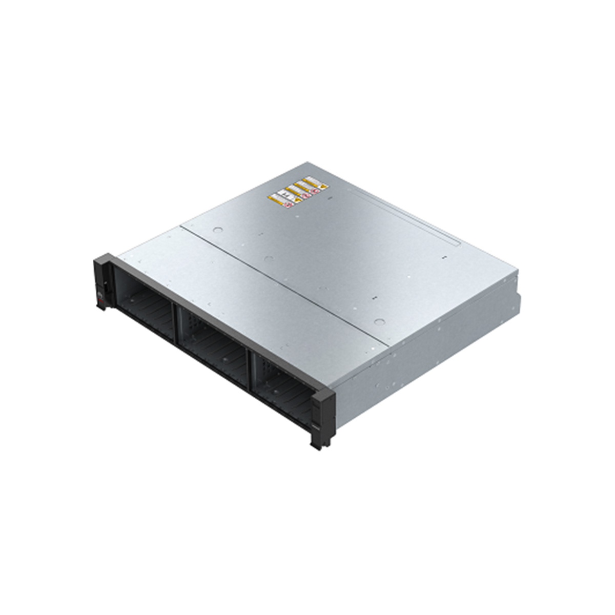
Switches support many power module models, which may have different dimensions and match different switch models.
To check whether the switch supports this power module, see the related product documentation or hardware query tool.
2. Checking Whether the Input Voltage and Power Cable of the Power Module Are Normal
If the switch cannot be powered on, perform the following operations to rectify the fault:
A. Ensure that the power switch is turned on.
B. Use a multimeter to measure the input voltage and determine whether the input voltage is normal according to the operating voltage range of the power module. Overvoltage and undervoltage may cause the power module unable to provide power.
C. Replace the current power cable with a new one to ensure that the power cable is not faulty.
3. Checking Whether Grounding and Environment Affect Power Supply
Fixed switches using built-in power modules are often deployed in a challenging environment, for example, low-voltage wells or corridors. In this environment, power modules have the protection mechanism. That is, at the moment when a switch is powered on, its power modules will check the power environment. If severe interference is detected, power modules do not provide power so that you will check the power supply status to reduce hardware failure rate.
In this situation, remove the power cable and wait for over 10 minutes for the interference to be led to the ground, and then power on the switch again. If power-on locking is caused by the interference, you are advised to optimize the live network environment. For example, ground the switch reliably or keep the power dispatching network stable to prevent frequently power-offs.

4. Checking Whether the Power Module Is Faulty
A. Remove and then reinstall the power module and power cable to ensure that the power module is securely installed.
B. Perform a cross test on the power module. Install the power module into another switch or use a normal power module of another switch to perform a cross test and rectify the fault. If the fault is caused by the power module, the power module is faulty.
5. Checking Whether the Power Module Indicator Status Is Normal
Table 1 describes the indicator on the power module panel of a modular switch and helps determine power fault types.
| Table 1 Description of indicators | |||||
| Power Module Type | Indicator | Color | Normal Status | Abnormal Status | Alarm Cause |
| DC power module | Running indicator (INPUT) |
Green | On | Off | The switch is not provided with -48 V power or the input voltage is low (lower than 30 V). |
| Fault indicator (ALARM) |
Red | Off | On | The fuse of surge protection circuits is damaged. Lightning strikes cause varistors to be short-circuited and so the fuse is blown. This fault will not affect power supply but the power module does not have the surge protection capability. |
|
| AC power module | Running indicator | Green | On | Off | The power module enters the protection state or is faulty. |
| Protection indicator | Yellow | Off | On | Recoverable protection (overtemperature or overcurrent protection) occurs on the power module. The indicator blinks yellow when communication is interrupted. |
|
| Fault indicator | Red | Off | On | The power module experiences unrecoverable faults, including overtemperature, output overcurrent, dual-fan fault, output overvoltage, external short-circuit, and no output. NOTICE: This indicator is colorless when the panel indicator is off and is green, yellow, and red when the running indicator, protection indicator, and fault indicator are on. |
|
6. Checking Whether Power Supply Alarms Are Generated on the Switch
If a modular switch can be powered on but power module alarms are displayed in the display alarm command output, rectify the fault according to the following table.
| Table 1 Power supply alarm handling | |||
| Power Module Type | Power Supply Alarm | Description | Suggestion |
| DC power module | DC PWR_FAULT | The external power source does not provide power. | Check whether the external power source provides power. |
| DC PWR_LACK | The external power source experiences input undervoltage. | Measure the voltage of the external power source. Ensure that it can provide power normally. | |
| DC SWITCH_STA | The power switch is turned off. | Ensure that the power switch is turned on. | |
| DC FUSE_FAULT | The fuse of the power module is damaged. | Check whether the external power source has an overvoltage condition. If the voltage of the external power source is normal, replace the power module. | |
| AC power module | AC PWR_FAULT | General power module alarm | 1. Check whether the CMU is available. 2. Check whether the input voltage is correct (whether the undervoltage or overvoltage occurs). 3. Remove and then reinstall the power module or install it into another slot. |
| AC MODE_FAULT | The power module experiences output overvoltage, does not output voltage, or has a fan fault. | 1. Check whether the CMU is available. 2. Check whether the input voltage is correct (whether the undervoltage or overvoltage occurs). 3. Remove and then reinstall the power module or install it into another slot. |
|
| AC MODE_ROTECT | The power module experiences overtemperature, overcurrent, overvoltage, and undervoltage protection; or the air breaker of the power module is switched off. | 1. Check whether the CMU is available. 2. Check whether the input voltage is correct (whether the undervoltage or overvoltage occurs). 3. Remove and then reinstall the power module or install it into another slot. |
|
| AC DROP | The power module experiences a power failure. | Check whether the power cable connected to the power module is loose or broken. If so, connect the power cable properly. | |
| AC FAN_FAULT | Fans of the power module have failed. | Remove the power module, listen to the sound of its fans, and then replace the power module. | |
7. Collecting Information and Seeking Technical Support
If the fault persists, collect related information and seek technical support.
Collecting Fault Information
Collect operation results of the preceding steps and record the results in a file.
Collect all diagnostic information and export the information to a file.
Run the display diagnostic-informationfile-name command in the user view to collect diagnostic information and save the information to a file.
<HUAWEI> display diagnostic-information dia-info.txt
Now saving the diagnostic information to the device
 100%
Info: The diagnostic information was saved to the device successfully.
When the diagnostic file is generated, you can export the file from the device using FTP, SFTP, or SCP.
NOTICE:
You can run the dir command in the user view to check whether the file is generated.
You can also run the display diagnostic-information command and save terminal logs in a diagnostic file on a disk.
If this command displays a long output, press Ctrl+C to abort this command.
This command displays diagnostic information, which helps locate faults but may affect system performance. For example, CPU usage may become high. Therefore, do not use this command when the system is running properly.
Running the display diagnostic-information command simultaneously on multiple terminals connected to the device is prohibited. This is because CPU usage of the device may obviously increase and the device performance may be degraded.
Collect the log and trap information on the device and export the information to files.
Run the save logfile all command in the user view to save the logs in the user log buffer area and diagnostic log buffer area to the user log file and diagnostic log file, respectively.
<HUAWEI> save logfile all
Info: Save logfile successfully.
Info: Save diagnostic logfile successfully.
When the diagnostic file is generated, you can export the file from the device using FTP, SFTP, or SCP.
NOTE:
You can also run the display logbuffer and display trapbuffer commands to view the log and trap information on the device, and save the information in diagnostic files on a disk. If need any technical support, please contact csd@telecomate.com for help.
NOTE:
Technical support personnel will provide instructions for you to submit all the collected information and files, so that they can locate faults.


Leave a comment